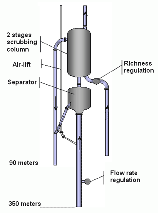
 Diagram of an extraction column. | DESCRIPTION OF THE COLUMN.The diagram opposite shows the gas extraction column. It is made up of 330 m of PEHD polyethylene tubes under the separator. A flow regulator for the column is placed at a depth of 100 m. The column is then attached to the base of the first unit, the separator. The gas lift is connected 20 metres below the separator on the main column, that is to say at a total depth of about 40 m. The supply pipe for the gas lift is a narrow gauge PE tube. The separator is a metal cylinder inside which the gas is separated from the water . Two outlets are joined to the separator, one to return the water to the depths (below), the other for the untreated gas (above). The water outlet rejoins the column
of waste washing water, whereas the the gas outlet directly rejoins the second
unit, the washing column. | |||
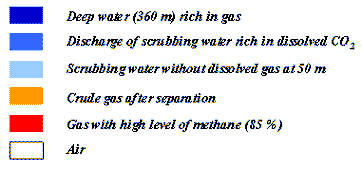
 Diagram of movement of liquid in the system | Flow inside the columnThe figure opposite illustrates the circulation of different liquids
in the system during the process of separation and washing of gas.

| |||